www.BadgerTrek.comAbout/ContactWeb LogOur Camper Van
Resources:Hobbies:MotorcyclesAmy's CakesOutboard Hydroplane RacingRadio Controlled Toys |
Camper Van Electrical System
The electrical system in our van is fairly involved as much of what we do for employment and entertainment is electrically dependant. The basics of the system were included in our initial order of the van from Sportsmobile, but we have changed, added, and replaced components till not much of the original system remains.
Essentially the system consists of two large "house" batteries that are charged from solar panels, the engine alternator when driving, or "shore power" when we plug into a regular outlet at a park or someone's house. From the batteries we obtain 120v AC power from an inverter for some items, and the rest (lights, computer, etc) runs directly off of the 12v DC provided by the batteries. We have spent a fair amount of time and effort to select electronics that run off of 12v so we do not often need to run the inverter (which is inefficient for running things that usually convert back to 12v DC internally anyway)
I attempt to describe each of the major components in some detail below, along with what we changed in regards to that piece of the puzzle.
Batteries (424Ah @ 12v theoretical):
- 2 x Lifeline/Concord 212Ah 12v 4D AGM batteries for storing energy for later usage
How It Came:
The van came with a single 4D Lifeline AGM battery mounted outside the driver's side frame rail behind the driver's seat. It sat in a tray made of steel angle-iron hung from the roof of the cabin.
Changes:
As winter came we found that the capacity of a single battery was not sufficient for the many days we would find ourselves socked in by poor weather without wishing to drive around or run the engine just to charge the battery. With the moving of the heat-exchanger and associated plumbing inside (see plumbing page) there was room behind the first battery for a second if a new tray was constructed to hold them together. The second battery was a Concord 212Ah 12V 4D AGM, which has all the same specs and manufacturer as the original Lifeline, just a different name and lower price. I built a new battery tray out of some 2"x1/8" angle iron and hung it with the two stock hangers and a couple all-thread rods between the batteries. This slightly more than doubles our capacity (taking into account the peukert effect: that batteries are more efficient at lower current draws, and now each battery only sees half of the current draw from a given load)
After adding the second battery we experienced a number of days where we were camped in near 0 degree F temperatures, and the voltage of the batteries increased significantly over nominal. This lead to us wrapping the battery tray sides and bottom with 1" of foam insulation to help keep the batteries warm. Battery temperature monitors have also been added to report the battery temperature to the various electronics which charge and monitor the batteries so they can compensate for the effects of temperature on the batteries.
Solar Panels (362watts theoretical):
- 2 Solara 56watt semi-flexible panels mounted on top of Thule roof box.
- 2 Kyocera 125 Watt
flat panels mounted to front of penthouse roof
How It Came:
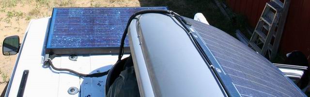
The van was ordered with 2 56 watt semi-flexible Solara panels installed on the roof. The panels were in line down the center of the roof, putting the 2nd panel in the shade of anything put on the roof-rack. Since solar panels pretty much shut off if even a portion of them is in shade, this made the second panel useless. Furthering our irritation here is the fact that we were assured that the panels would be placed side-by-side up front when we were spec'ing out the van with Sportsmobile in February. In addition, some of the external wiring for the panels also crossed the active part of the panels, and caused a measurable reduction in the panel efficiency due to the shadows cast over the cells (output went from 4.1amps to 5 just by moving the wires out of the way) .
Changes:
We first added an 80watt solar panel to the roof and moved the Solara flexible solar panels onto the top of the Thule roof box. Removing the Solara panels was quite a task, as they were glued to the roof with neoprene glue, and also screwed down with sheet-metal screws.
The 80watt panel was bolted onto aluminum Z rails to account for the curvature of the roof, and allowing airflow underneath for cooling of the panel (hot panels don't work as well, and they get HOT in the sun).
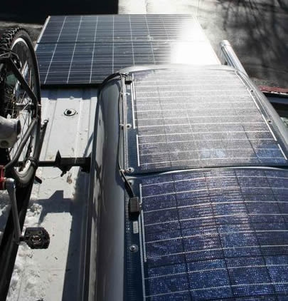
A few months later we replaced the front 80watt panel with 2 Kyocera 125 watt solar pannels. Instead of re-using the Z rails, we used two 4' lengths of aluminum angle, screwed and bolted to the roof, and then pop-rivited the panels to the angle. Removal of the panels will require drilling out the rivets, but hopefully will never be required.
After some time we noticed that the solar input seemed lower than expected for the time of year, but would fluctuate, sometimes matching expectation. Finally tracked it down to the "flexible" Solara solar panels. One of them had a number of cracks in the tinned copper traces running between the constituent cells. It appears that when it had been trod upon, the sharp edges of the silicon wafers had cut the traces that transitioned over the edges of the cells. Just flexing the panel a bit would drastically change its current output. I carefully examined each trace at the transition points, cut out the rubber coating over each one that appeared cracked, soldered the cracks, and re-sealed the cuts. Panel output became high and consistant.
After a couple more years the covering on the Solara panels begain to release from the panels leading to hazy spots and introduction of water into the panel interior. This has put a significant dent in the output they provide and we will likely remove them in the near future. This may have been caused by the flexing they experience on the roof-box, or perhaps the adhesive is just not up to years of weathering.
Solar Charge Controller:
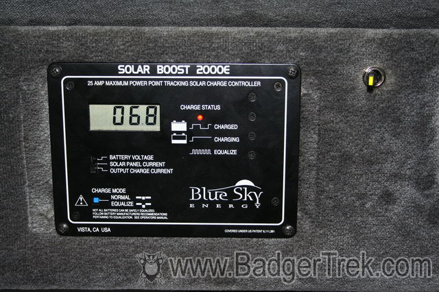
- Solar Boost 2000E with battery temp sensor to control charging of batteries from solar panels.
How It Came:
From Sportsmobile the solar system was run by a Specialty Concepts Mark 22 charge controller. Internally the solar controller was mounted in the head-liner behind the couch. The installation looked nice, though the hole cut was a bit oddly-shaped and big, so only 2 of the four screws mounting it actually went into wood, the other two just sat there and vibrated out slowly as we drive.
The charge controller had a battery voltage display, however after comparison with 3 other volt meters, it read about 0.2v low, which is very significant in reporting state of charge of a lead-acid battery.
Changes:
We traded out the standard charge controller (Specialty Concepts Mark 22) for a Blue Sky Energy Solar Boost 2000E MPPT 25amp charge controller. This offers a number of benefits:
- It actually fits the mounting hole better than the original charge controller.
- The new charge controller contains a DC-DC voltage converter that allows the panels to run at their optimum voltage (about 17) and down-converts the output voltage to charge the battery, resulting in a significant efficiency gain (we saw about 20% increase in battery charge current the day we swapped the controllers, and this takes no new panel area)
- Over-current situations do not result in a blown-fuse. The controller just pumps the current it can into the batteries (up to 25A). With our additional panels (which may be capable of more than 25A if the van tilts appropriately when driving on a sunny day) we were concerned that we would need to unplug some panels in the summer if we might be driving on significantly south sloping terrain, this is now not an issue.
- The volt-meter in the display is much more accurate than the old one.
- A battery temperature sensor was available to adjust the charge voltage as necessary
- In the summer we found that we were almost always running at near full charge. Since the charge controller does not have a "float" stage for when the battery is full a 30 amp switch was installed to allow us to turn off the solar array when there was no need to keep charging the batteries. This helps keep the battery temperature down as well.
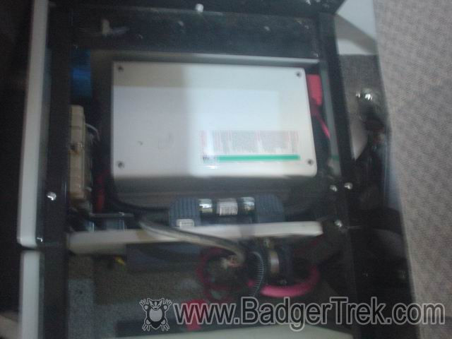
Inverter/Battery Charger:
- Trace (Xantrex) UX1512SB 1500watt inverter with battery temp sensor to provide 120vAC when not plugged into shore power, and to charge batteries from shore power when plugged in.
How It Came:
We ordered the van without an inverter. The one provided by Sportsmobile was overkill for our needs, and we were not initially sure if we wanted one. There were 3 120v outlets in the cabin but they were only powered when the van was plugged into shore-power. For charging Sportsmobile had installed what was essentially a 13.6v switching DC power supply that plugged into a hidden 120v outlet under our sofa.
Changes:
My father had an extra Trace (Xantrex) UX1512SB inverter with battery charger floating around, so we installed that in place of the battery charger under the sofa. This provides up to 1500watts of modified-sine AC, which is more than plenty of capacity for any use we have ever found for it. When we are plugged into shore power it will manage the charging of the house battery. This inverter also has a "search" mode which allows it to not turn fully on until a sufficient load is plugged in. Since the inverter draws about 7watts when on, but less than 1 watt when in search mode this can be a significant power savings over an inverter without such a feature.
We also added a 100 amp fuse on the positive line from the house-batteries when installing the inverter as no fuse was in place as the system came from SMB, which seemed unwise to us.
Come winter and cold temperatures we found the batteries would not get fully charged even when we were plugged in due to the increased voltage of a cold battery. We solved this problem by installing a battery temperature sensor that lets the charger electronics know the temperature of the battery bank it is charging and adjust the charge voltage appropriately.
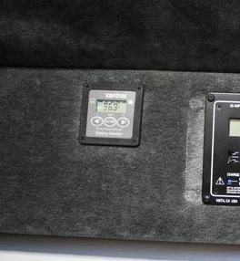
Monitoring:
- Xantrex Battery Monitor
(XBM) with battery temp sensor to keep track of battery charge and state
How it came:
When living off the grid obtaining power from various sources and storing it in batteries, a very important piece of knowledge is how much charge is actually in the battery bank at any given time. This lets you know whether the batteries can be drawn down more, or if you should conserve today, or if there is a problem with a battery.
The only monitoring mechanism provided, when we got the van, was a volt meter built into the solar controller. The utility of this is based on the concept that lead-acid battery voltage indicates the state of charge. There are a couple flaws in this reasoning for an actively used system however: the voltages usually listed in tables are only valid for batteries around room-temperature (about 68deg F) and the voltage is only meaningful for batteries which have been idle for a few hours (no charge or draw in that period). A second, related, problem was that the volt meter built into the charge controller read low by about 0.2v.
Changes:
At the same time we installed the solar controller (which provided a much more accurate volt meter) we also added a Xantrex Battery Monitor which includes a shunt so that it can measure, and then integrate, the current draw and charge that the battery bank sees.
The monitor provides information on net house-battery current ( = input - charge to van batteries - usage - loss), voltage, percent charged, amp hours used, charge efficiency of the batteries, etc. Using this we can see: how full the batteries are, how much instantaneous charge we are getting total (panels, charger, alternator), how much current various appliances use (which can be surprising (2.4a fridge when running, 0.6a computer when OFF, 0.2a monitor when OFF, etc)). It also allows us to see the difference between what is coming in from the panels, and what actually reaches the house batteries (some goes to the engine batteries, some to drive the separator solenoid, etc)
As with the inverter/charger and the solar charge controller, the battery monitor has a battery temperature sensor. In this case it is used to accurately model the behavior of the battery bank, and make sure the monitor can accurately compensate for battery capacity and charge characteristic changes due to temperature. It also allows us to read the current battery temperature on the display.
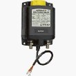
Battery Bank Separation
- BlueSea Systems Heavy Duty Automatic Charging Relay
with remote control contura switch
How it came:
The van came from Sportsmobile with a Surepower battery separator solenoid. This was wired to join the house battery and engine batteries in parallel whenever a charge was applied to either side. The idea is to keep both banks charged by input anywhere in the sytem (solar panels, alternator, plugging in charger), while seperating the battery banks when there is a net load so that usage of the household appliances does not risk draining the starting battery bank. Additionally the solenoid was wired to join the battery banks whenever the ignition was on, to assist in turning the starter.What we changed:
We experienced a few problems with the setup as it came, and made a series of changes over the years.
The first issue was the power draw of the Surepower unit. Whenever the battery banks were joined the solnoid was drawing about 1.3amps of current (about 16watts) just to keep the internal switch engaged. This was a good 10-20% of our power input when we were running just off of solar. Additionally this created a fair amount of heat, enough to burn one's hand if touching the solenoid after it had been engaged for a number of minutes.
We addressed this issue by adding a switch to optionally disengage the ground line of the solenoid so that it would not engage. We would turn this off when parked for an extended time so the solar panels were not trying to join the banks and charge the engine batteries too. This saved the power that would be wasted at the solnoid, and presumably the engine batteries should stay charged as they had no draw. When driving we would flip the switch on so that the battery banks could join and the alternator would charge both the engine and house batteries. The drawback to this was that it essentially removed the "automatic" feature of the solenoid, and sometimes we would forget to switch it.
The second issue was that after about 7-8 months of use the solenoid would appear to join, but we could see that no actual charge was going into the house battery from the alternator while driving. The solnoid would thunk on startup (expected as it engaged), and get hot, but no connection appeared to be made. We disassembled the solenoid and found that the contacts inside were covered in copper oxides from the terminals, some crystals of which had gotten between the contacts and were preventing physical joining. We disolved the oxides with some CLR (Calcium/Lime/Rust remover), and added a 6mo checkup/clean of the solenoid to our maintenance spreadsheet.
The third issue we encountered was with the way the solenoid was wired to automatically join the batteries when the ignition turned on. This probably reduces the load on the engine batteries a bit for startup, but completely masks the signs of a dying starting battery (since the house batteries just do all the work) till the starting battery is completely gone. After we went through a couple sets of engine batteries without realizing they were dead (till forgetting to throw the above mentioned switch to the solenoid, or the van wouldn't start at all) we decided the join on ignition was a bad idea and disconnected that line.
Finally we had a case where the engine batteries had died, we were ignorant of this because of the prior mentioned issue, and because the solenoid requires power (from the engine battery side) to actually join, we could not get the van started without manually throwing a jumper cable across the solenoid to get the house batteries to charge the solenoid up and get the join to occur.
By this point we essentially had a manual battery joining switch, except that it drew significant power, requried rather periodic maintenance to keep functioning, and when the engine batteries died we had to resort to jumper cables to force a join.
Eventually we decided to swap the SurePower unit out for a magnetic latching charging solenoid. These use magnets ,instead of a constant current, to keep the solenoid either joined or separated, which significantly reduces power consumption, and allows for a simple manual override by simply pushing the contactor slide to one end or the other.
Our final choice was a BlueSea systems heavy duty automatic charging relay with a remote switch and manual override capabilities. For most cases it would run in automatic, joining the batteries when charging occurs on either side, the remote switch can force a join (say to help with a start if the engine batteries fail), or force separation, and the manual override can force join or force separation if there isn't even enough power to throw the solenoid electrically. This addressed all of the issues mentioned above, and we have had (so far) no issues with corrosion internally (probably because of the lack of constant heat)
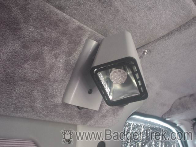
Lighting:
How It Came:
The lighting inside the cabin was mostly a set of fluorescent fixtures from Thinlite (which produce a nice warm light for a fluorescent fixture), but there were a few incandescent bulbs: The rear of the van, the cab reading lights, and the cabin reading lights. The incandescents draw significantly more power, and produce more heat, than an equivalently bright fluorescent or LED fixture.
Changes:
We replaced all the internal incandescent bulbs with LED or fluorescent fixtures.
We bought LED reading, cabin, and instrument bulbs and they work quite well, while pulling a tiny fraction of the power from our batteries. The color is a bit "cold" but not too bad. Illumination is less than the normal bulbs, but plenty for our uses most of the time at night (reading, eating, etc). One of the LED "bulbs" we bought has had most of its elemental LEDs go out, but the rest are doing fine. We upgraded some of the original 12element "bulbs" to 19 element ones after a few months, and would recommend these larger ones as it is a bit difficult to read by the smaller ones. The brand we purchased (www.superbrightleds.com) seem to have a common flaw that the LEDs start to go out after a while. Physically wiggling the elements will turn them back on so I believe the internal soldering or something is bad. This is common to all the 12 and 19 element bulbs we have tried.
For the rear van light (which seemed about to melt the plastic when we left it on for a while once), we pulled it out and put in a small GE 12v fluorescent fixture we found at a hardware store (intended to run on 8 AA batteries for a closet). We also added another of these fixtures above the cook-top, as it helps to see what is going on in your pot when its dark outside or the shades are closed up. For some reason we have now blown 4 of the GE units, and even at 8$ a piece, this adds up. We finally broke down and picked up a couple 40$ fluorescent fixtures intended for boat cabin lighting. They are a lot nicer and put out more light (13 watts of draw each). One is over the stove, and one over the rear doorway.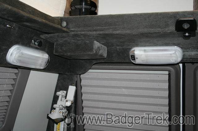
Wiring:
The wiring from the panels, and batteries go to a battery isolator, under the sofa, which joins the house battery to the engine's batteries when there is charging on either side, or the house battery is higher than the van batteries (i.e. for starting or jumping), but separates the batteries if the house battery is drawn down too low (so you don't discharge the engine's batteries). From the isolator the wiring runs through a DC circuit breaker to a fuse box for all the internal DC circuits (fridge, radio, lights, etc). This fuse box was not terribly impressive, and with the way the wires were installed, it could not even have the cover closed, presenting a shorting risk if anything metal were to get in there. We also finally tracked flickering lights down to the fusebox itself. Just bumping the fuses would cause intermittant contact of the circuits resulting in in the flickering when we walked around. Power lines for the Espar furnace and coolant heater were not routed through the fuse-box, but rather had inline fuse holders and the accompanying extra wire crimps that entailed.
For the wiring, most of plugs are on the passenger side with our layout, right in front of the sink and next to the fridge. There was one fairly heavy red wire leading into this area that was not plugged into anything, and seems to be floating electrically. I am wondering if this was intended to provide separate power for the water pump and passenger side accessories, since the water pump lead and the 12v plug were crimped together by a short jumper wire.
Most of the wiring is encased in split loom tubing for protection, which is a nice way of preventing wear and shorts. A few of the places the wires pass through holes are actually not protected, which seems to me to be where this would be of the most benefit. Nothing major though.
Behind the walls the wires are zip-tied together and screwed to the metal shell of the van, so maintenance and upgrades of the wiring is a difficult task. If conduit had been used new wires could be more easily fished through.
The radio is powered off of the van engine battery. Sportsmobile added a switch to force it on when the ignition is off, but they only provide an ignition signal, they do NOT provide power to the radio, so it will still drain the engine battery (also makes one wonder why SMB specifies a 15amp fuse for the radio ignition switch). As expected, the stock Ford 12v outlets in the dash are wired off of the van engine battery.
Changes:
- Re-arranged the wiring for the in-cabin fuse box so that the cover would close. Also added a second fuse box on the passenger side of the cabin to have more fine-grained control over current going to the stove, fridge, computer, etc (nice quality marine unit made by BlueSea). The entirety of the passenger side was originally controlled by a single fuse in the main cabin fuse block.
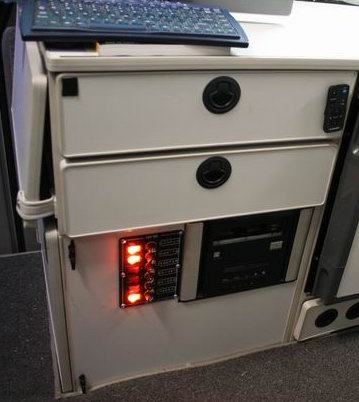
- Routed 110Vac and 12Vdc to a cabinet near the side cargo doors for use by the computer and various accessories in that cabinet. Added another BlueSea fuse box in this cabinet for finer grained control and protection of the electronics. Later replaced with a marine switch-panel with lit switches for indicating loads left on. The main computer sits in here and has its front poke through a hole in the side for access to the drives and switches.
- Added insulation to the refrigerator. Although this isn't directly related to the electrical system, it has a tremendous effect on the power usage as the fridge is our largest net power consumer since it is on 24/7. Details are on the appliances page.
- Ran power from the house battery to the front console for the radio and 12v outlets. This helps to protect the van battery from being sucked down by radio and other usage.
- Replaced speakers in the van with aftermarket ones with plastic cones. The paper cone speakers that come stock do not fare well with the humidity of being in a small RV. Plus the new ones sound much better.
- After a year and a half, replaced the main fuse-box with a BlueSea marine fuse-box with 12 circuits and much more solidly built. Lights no longer flicker when walking past the fuse-box.
- Ran the coolant heater and furnace to the new fuse-box and removed the extra crimps and inline fuse holders.